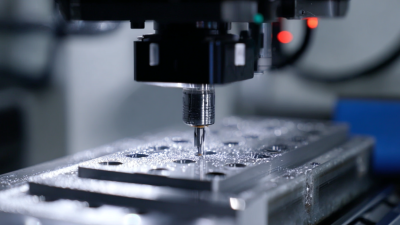
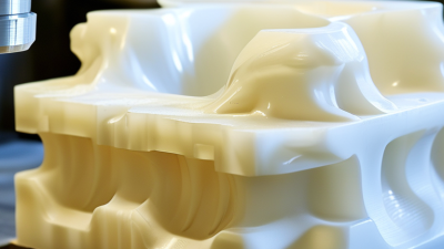
Injection molding rewards thoughtful design long before a mold reaches the press. Small decisions affect filling, cooling, ejection, surface quality, and production cost. A wall that looks harmless on a screen may create a sink mark beside a rib. A sharp internal corner may concentrate stress and complicate machining. Practical design for injection molding connects part geometry with material behavior, tooling limits, and repeatable manufacturing.
This guide presents ten design tips used by product engineers, mold designers, and experienced manufacturers. It examines wall thickness, draft angles, ribs, bosses, corners, parting lines, gates, cooling, tolerances, and material selection. Each topic links a design choice to a visible result, such as warpage near a thick section or drag marks on an undercut. Good guidance must be specific.
But no checklist solves every project. Material grades vary. Mold layouts create trade-offs. A feature that works in glass-filled nylon may fail in polypropylene. Early moldflow analysis can reveal risks, yet simulation is not a substitute for shop-floor judgment. Even experienced teams revise designs after reviewing first-off samples. That is normal.
Look closely. Feel the edge.
Reliable results come from collaboration between design, tooling, and production teams. Engineers should confirm assumptions with resin suppliers and moldmakers before releasing final geometry. Clear drawings, realistic tolerances, and documented testing also support consistent quality. The following tips are intended to improve decisions, not replace engineering review. Some recommendations may need adjustment when appearance, strength, cycle time, or budget becomes the dominant priority.
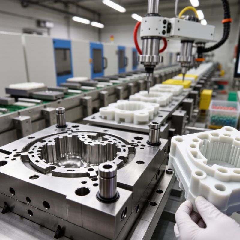
A successful injection-molded part begins with its function, not its appearance. Define the load, movement, temperature, and expected service life before drawing detailed geometry. A housing needs impact resistance, while a clip may need repeated flexibility. These requirements change wall thickness, ribs, bosses, and tolerances. I have seen attractive prototypes fail because their snap fits were tested only once.
Material choice should support real operating conditions. Compare strength, stiffness, chemical exposure, moisture absorption, shrinkage, and heat resistance. A material that works in a dry office may deform near an engine or cleaning solution. Confirm the data through supplier specifications and physical testing. Do not rely on a familiar resin without checking the latest requirements. Small assumptions become expensive mold changes.
Manufacturing requirements must enter the design early. Use consistent wall thickness where possible, add suitable draft, and place ribs carefully to reduce sink marks. Keep gates, parting lines, and ejection areas in mind. A deep, polished cavity may look impressive, but it can increase tooling cost and removal force. Leave room for measurement and process variation. Perfect dimensions on paper are not always practical. A first design is rarely correct. Review sample parts, record defects, and adjust based on evidence rather than preference.
Injection-molded parts fail most often at transitions, not on flat surfaces. A 2024 industry market report valued global injection-molded plastics demand above USD 180 billion, increasing pressure for lighter, repeatable designs. Industry design data from the Society of Plastics Engineers recommends keeping many thermoplastic walls near 1.5–3 mm. Uniformity matters more than extreme thinness. A 0.5 mm change can create visible sink, warpage, or uneven cooling. I have seen attractive prototypes fail because the wall looked “almost uniform.”
Tip: Keep wall variation within roughly 10–15% where possible. Use gradual transitions, generous internal radii, and draft near 1 degree per 25 mm of wall depth. Shorter flow paths reduce pressure demand. They also reduce hesitation marks.
Tip: Design ribs at 40–60% of the main wall thickness, according to widely used injection-molding design guidelines. Keep ribs away from cosmetic surfaces when sink marks matter. Add fillets at rib bases instead of sharp corners. For bosses, use about 50–60% of the surrounding wall thickness. Support them with ribs, but avoid creating a thick central mass. ISO 20457 tolerance guidance also shows why shrinkage must be considered early, especially around bosses and inserts. These ratios are starting points, not laws. Material grade, tooling steel, cooling layout, and gate position can change the result. Prototype the critical feature. Then measure it.
| No. | Design Feature | Recommended Guideline | Typical Target or Range | Why It Matters | Design Check |
|---|---|---|---|---|---|
| 1 | Maintain Uniform Wall Thickness | Keep the main walls as uniform as practical and avoid abrupt changes in section thickness. | Common thermoplastic parts: approximately 1.5–3.0 mm, depending on resin, flow length, and part size. | Uniform walls reduce differential cooling, sink marks, warpage, residual stress, and inconsistent filling. | Review wall maps and identify isolated thick zones or sudden thickness transitions. |
| 2 | Use Gradual Thickness Transitions | Transition between different wall sections with tapers, radii, or stepped changes rather than sharp thickness jumps. | Where feasible, use a gradual transition over several wall thicknesses; avoid concentrated mass at intersections. | Gradual transitions improve melt flow and reduce stress concentration and visible read-through. | Check corners, transitions, and molded-in features for abrupt changes in volume. |
| 3 | Size Ribs for Stiffness Without Sink | Use ribs to increase bending stiffness instead of making the entire wall thicker. | Rib thickness: about 40–60% of the adjoining nominal wall; rib height: commonly up to 2.5–3 times wall thickness. | Thin, properly proportioned ribs improve stiffness while limiting sink marks and cooling-related distortion. | Use a draft angle and inspect the rib-to-wall junction for excess material buildup. |
| 4 | Apply Draft to Vertical Faces | Add draft to surfaces parallel to the mold opening direction, especially textured or deep surfaces. | Typical starting point: about 0.5–1° per side for smooth surfaces; more for texture, depth, or difficult release conditions. | Draft reduces ejection force, scuffing, drag marks, and the risk of part deformation. | Confirm the draw direction and measure draft on cores, cavities, ribs, bosses, and shutoff surfaces. |
| 5 | Design Bosses Around Their Function | Use hollow bosses with supporting ribs or gussets rather than solid bosses with excessive material. | Boss wall: approximately 40–60% of nominal wall; provide clearance around inserts or fasteners as required. | A properly cored boss supports screws or inserts while reducing sink, voids, and cooling time. | Check boss concentricity, screw engagement, pull-out loads, and the surrounding wall for sink risk. |
| 6 | Add Radii to Corners | Replace sharp internal corners with generous radii and maintain a balanced relationship between internal and external radii. | Internal radius: commonly at least 0.5 times the nominal wall thickness; use larger radii for highly stressed areas. | Radii improve melt flow, reduce stress concentration, and make the part and mold less vulnerable to cracking. | Review load-bearing corners, flow fronts, and regions exposed to impact or repeated flexing. |
| 7 | Control Undercuts and Side Actions | Avoid unnecessary undercuts; use mold-opening direction features whenever possible. | Eliminate or simplify undercuts before adding lifters, slides, collapsible cores, or other mechanisms. | Simpler tooling generally reduces mold complexity, cycle time, maintenance requirements, and tooling risk. | Perform a parting-line and mold-kinematics review before design release. |
| 8 | Plan Ribs and Features for Mold Filling | Arrange structural features to support balanced filling and avoid isolated end-of-fill traps. | Use flow analysis for long flow paths, thin walls, multiple gates, or complex feature networks. | Feature layout affects weld lines, air entrapment, pressure demand, filling time, and cosmetic quality. | Check predicted weld lines, air traps, pressure, temperature, and volumetric shrinkage. |
| 9 | Use Gussets Strategically | Add gussets near bosses, brackets, and load paths to improve rigidity without creating large solid sections. | Keep gusset thickness near the rib guideline, typically about 40–60% of the adjoining wall. | Gussets distribute loads and reduce flexing while limiting local mass and sink-mark risk. | Confirm that gussets do not interfere with ejection, assembly clearance, or mold steel strength. |
| 10 | Validate Shrinkage, Warpage, and Ejection | Combine material data, mold-flow simulation, tolerance analysis, and prototype or trial molding results. | Use the selected resin supplier's shrinkage data and processing window; do not rely on a single universal shrinkage value. | Material grade, fiber orientation, cooling balance, gate location, and processing conditions strongly influence final dimensions. | Verify critical dimensions, flatness, assembly fit, ejection marks, and appearance after conditioning. |
In injection molding, easy ejection begins long before the mold opens. Draft angles reduce wall friction and protect surfaces during release. Keep it simple. Smooth walls often need 0.5 to 1 degree of draft. Textured surfaces may require more, depending on texture depth and material behavior. A deep rib without enough draft can drag, whiten, or deform during ejection. I have seen a small angle change eliminate repeated scuff marks on a molded part.
Sharp corners create trouble. Internal fillets improve resin flow and reduce stress around ribs, bosses, and pockets. External radii should support the same transition without creating unnecessary bulk. A practical starting point is an internal radius near half the wall thickness. However, generous fillets can affect fit, appearance, or cooling, so they need review in context. “Bigger is better” is not always true.
Transitions deserve equal attention. Sudden wall-thickness changes can produce sink marks, warpage, and uneven cooling. Blend thick bosses into nearby walls with ribs instead of heavy intersections. Ribs commonly stay near 40 to 60 percent of the nominal wall thickness, then require testing or simulation. This range is only a guideline. Before design approval, inspect draft, parting lines, ejector locations, and shrink direction together. I once approved a clean CAD model that needed hand rework because ejector pads touched a flexible area. Section views, molded samples, and measured ejection force can expose these hidden risks.
Draft angles shown are typical starting points for smooth, untextured molded surfaces. Actual requirements vary with part depth, surface texture, shrinkage, tooling steel, and ejection force. Add generous internal fillets, avoid abrupt wall-thickness changes, and validate the design with the mold maker.
A reliable mold begins with controlled polymer flow. Place the gate near the thickest section when possible. This reduces hesitation and limits visible sink marks. Fan gates can spread flow across wide surfaces, while pin gates suit smaller, precise entry points. Gate location still needs testing. Cosmetic expectations often change the best choice.
Design runners with balanced lengths and suitable diameters. Unbalanced runners can fill one cavity early and leave another short. That difference may create uneven packing, warpage, or inconsistent weight.
Keep runners smooth and avoid sharp corners. Small radii can increase pressure loss. They look harmless.
Vents need a clear escape path for trapped air and gas. Put them near weld lines, last-fill regions, and deep ribs. A blocked vent can cause burns, hesitation, or incomplete filling. Cooling channels should follow the part’s geometry, not merely the mold plates. Maintain even spacing around thick areas. Add closer cooling near bosses when practical.
Conformal paths may improve uniformity, but conventional drilling remains easier to inspect and repair. I have seen excellent layouts fail because cooling lines were difficult to clean. That detail is easy to overlook.
Measure mold temperatures during trials, then adjust flow before changing the whole design. Some defects need better venting, not colder water.
Tolerances should follow function, not designer habit. ISO 20457 separates molded-part tolerances by manufacturing capability and material behavior. Tight dimensions increase tooling, inspection, and rejection risks. A practical target is often ±0.1 mm only when the assembly truly demands it.
Check shrinkage early. Glass-filled materials can distort differently from unfilled grades. Warpage may appear around ribs, bosses, and uneven wall sections.
I have seen a perfect CAD model fail because one mounting hole moved after cooling.
Surface finish also affects release, appearance, and assembly. The SPI Mold Finish Guide defines 12 finish grades, from high-gloss polished surfaces to textured finishes. Polishing a deep cavity can be difficult and expensive.
Texture needs draft. A common starting point is about 1 degree of draft per 0.025 mm of texture depth, although resin and geometry change the result.
Keep wall thickness as uniform as possible. A 2.5–3 mm wall is often easier to fill than a thin, irregular section, but the correct value depends on resin and flow length.
Assembly deserves review before mold steel is cut. Add lead-ins, clearance, and visible access for fasteners. Avoid forcing flexible parts over sharp edges.
The U.S. Department of Energy’s Manufacturing Energy and Carbon Footprints reports show that plastics processing consumes substantial process energy, so failed trials are not harmless.
Prototype the joint. Then challenge the tolerance stack. Some designs still work with looser dimensions, and that uncomfortable discovery can save a mold revision.