
No Job is Too Big or Too Small!
Top 10 Design for Injection Molding Tips for Buyers
Injection-molded components are found in everyday products, from appliance housings to automotive connectors. Yet a low unit price does not guarantee a low total cost. A poorly placed rib, sharp corner, or hidden undercut can increase tooling complexity, extend cycle times, or complicate part removal. Small details matter.
The scale is substantial. PlasticsEurope’s Plastics – the Fast Facts 2024 reports 413.8 million tonnes of plastics production worldwide in 2023. That figure covers plastics production overall, not injection molding alone; it provides industry context, not a process-specific forecast. For buyers, the practical question is how a part’s geometry, resin, tolerances, and expected volume work together. A thin wall may save material, but it can also create filling or warpage concerns. The right choice depends on the application and the supplier’s process.
This guide presents 10 design for injection molding tips buyers can use when reviewing parts and requesting quotes. It covers wall consistency, draft, ribs, bosses, undercuts, material selection, and communication with mold makers. It also highlights questions worth asking before tooling begins. For example: where does the gate go, and how will the part be ejected? These details can be easy to overlook on a polished CAD screen. A checklist helps, but it cannot predict every production surprise. Treat the recommendations as discussion points, then validate critical features with an experienced manufacturing partner.
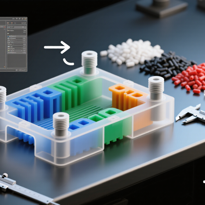
Define Part Requirements and Production Goals
Before requesting an injection-molded part, define what it must do in its finished product. Note the expected load, operating temperature, exposure to moisture or chemicals, and acceptable surface appearance. A small housing may need a smooth face, while hidden clips may prioritize flexibility. Specify critical dimensions and tolerances, but avoid demanding tight tolerances everywhere. They can increase tooling and inspection costs without improving performance. Small details matter.
Tips: Share a sketch or sample with clear measurements. Mark the surfaces users will see and identify features that affect assembly. Include expected annual volume and likely order sizes. These details help suppliers assess material, tooling, and process choices more accurately.
Set production goals before comparing quotations. Clarify the target part cost, launch date, forecast changes, and whether the design may be revised. A simple production estimate is more useful than an unsupported “high volume” label. Ask how the quoted cycle time and expected scrap rate were estimated. Early requirements are rarely perfect; that is normal. Review assumptions with the engineering and purchasing teams, especially when the part has thin walls, snap fits, or visible cosmetic surfaces. A missed requirement can lead to costly mold changes later.
Top 10 Design for Injection Molding Tips for Buyers - Define Part Requirements and Production Goals
| # | Design consideration | What buyers should define | Practical action |
|---|---|---|---|
| 1 | Part function and critical features | How the part is used, assembled, loaded, and inspected; identify safety-related and fit-critical features. | Mark critical-to-function dimensions on the drawing and specify how they will be measured. |
| 2 | Material and operating environment | Required strength, stiffness, impact performance, temperature range, chemical exposure, color, and applicable compliance needs. | Select a specific resin grade with the molder; account for shrinkage, moisture sensitivity, and property trade-offs. |
| 3 | Annual volume and demand pattern | Expected annual quantity, order size, forecast variation, product life, and possible demand growth. | Compare tooling and piece-price options against realistic volumes, including low-volume launch and future demand scenarios. |
| 4 | Wall thickness and transitions | Structural needs, appearance requirements, and areas where thickness changes cannot be avoided. | Aim for reasonably uniform walls and use gradual transitions; review thick sections that can cause sink or voids. |
| 5 | Draft and part release | Surface finish, texture, draw direction, and any areas that must remain free of visible marks. | Include draft on molded walls. As an initial guideline, many parts use about 1–2° on smooth surfaces; textured surfaces may need more. Confirm with the toolmaker. |
| 6 | Radii, corners, ribs, and bosses | Load paths, fastening needs, appearance constraints, and allowable local thickness. | Use radii instead of sharp internal corners where feasible; size ribs and bosses to reduce stress concentration and sink risk. |
| 7 | Undercuts and side actions | Features that prevent straight release from the mold and whether they are essential to function. | Review openings, snap features, and threads early; redesigning to avoid side actions can reduce tool complexity and cycle time. |
| 8 | Tolerances and shrinkage | Which dimensions control fit or performance, and which can use broader limits. | Apply tight tolerances only where needed. Discuss resin, geometry, measurement method, and process capability before finalizing limits. |
| 9 | Gate, parting line, and ejection marks | Visible surfaces, sealing areas, assembly interfaces, and acceptable locations for tool marks. | Agree on preferred gate and parting-line locations with the molder; provide a cosmetic-zone map when appearance matters. |
| 10 | Tooling, validation, and launch goals | Tool life, number of cavities, sampling plan, approval criteria, delivery dates, and ownership or maintenance expectations. | Set acceptance criteria before tooling begins and plan trials to verify dimensions, appearance, assembly, and production readiness. |
Note: Guidelines are starting points; final design decisions depend on part geometry, resin grade, tooling strategy, and production conditions.
Related Posts
-
Top 10 Design Tips for Injection Molding
-
Top 10 Essential Injection Molding Tooling Techniques for Efficient Production
-
Innovative Techniques for Optimizing Design for Injection Molding in Modern Manufacturing
-
How to Choose the Right Injection Molding Tooling for Your Project
-

What is Design for Injection Molding and Why It Matters?
-
China Best Injection Molding Small Parts Manufacturer?